Considerations for Generator Set Foundations
Foundations supporting generator sets must meet flotation, alignment and vibration parameters for successful operation. Specifications that consider the following criteria will help assure trouble-free installation and operation.
Foundations must be able to withstand the installation’s weight and prevent deflection. To determine the pressure exerted by a generator set, use the following equation:
P = W/A
Where:
P = pressure in PSI (kPa)
W = generator set wet weight in lbs (kg)
A = Area in sq. in. (m2) of the rails, pads or vibration mounts.
This pressure must be less than the load-carrying capability of the soil foundation pad. General load bearing capabilities of underfoot are listed in Table 1.
Table 1 Bearing Load Capacities
| Safe Bearing Load | ||
| Material | psi | kPa |
|---|---|---|
| Rock, hardpan | 70 | 482 |
| Hard clay, gravel and coarse sand | 56 | 386 |
| Loose medium sand, and medium clay | 28 | 193 |
| Loose fine sand | 14 | 96.4 |
| Soft clay | 0 – 14 | 0 – 96.4 |
The foundation should weigh at least as much as the generator set’s wet weight. Use this equation to calculate the necessary foundation depth:
Foundation depth = W/DxBxL
Where:
W = Total wet weight of gen set (lb or kg)
D = Density of concrete (150.b/cu.ft3 or 2,400 kg/m3)
B = Foundation width (ft or m)
L = Foundation length (ft or m)
This equation assumes a concrete mixture ratio of 1:2:3 (cement:sand:aggregate) with maximum 4 inch (101.6mm) slump and 29-day compressive strength of 3,000 psi (20.67MPa).
If no vibration isolators are used, the floor must support 125 percent of the generator set weight. If generators sets are paralleled, possible out-of-phase paralleling could cause torque reactions. Here, foundations must be designed to withstand twice the generator set wet weight.
Outside base dimensions should extend beyond the unit a minimum of 1 foot (304.8mm) on all sides. Foundation footings must extend below the frost line.
The foundation should be reinforced with No. 8 gauge steel wire fabric of No. 6 reinforcing bars on 12-inch (304.8mm) centers horizontally. Bars should be imbedded in the concrete at least 3 inches (76.2mm) from foundation surface.
Maintaining Alignment
Modern multi-cylinder medium-speed generators sets do not require massive concrete foundations to maintain engine/generator alignment. In most applications, a single-bearing generator set can be installed and operated on the base it was shipped on.
Two-bearing generators, generators driven from either end of one engine, tandem generators or generators with tandem engines require much heavier boxed base that resists bending forces exerted by the generator sets. The base also must prevent resonant vibration during operation.
Flexible Connections
Any supply line or hose connected to the generator set–including exhaust coupling and exhaust pipe hangers, jacket water connections, heat recovery systems and fuel lines–must be fitted with a flexible section that can withstand vibrations incurred by the operating generator set. These flexible connections should be installed as close to the generator set as possible and be designed to prevent line leaks or breaks.
Service Considerations
Convenience and serviceability can be designed into a generator set foundation. Consider specifying conduit for electric starting systems, generator leads and fuel and water connections.
Generator Set Vibration Isolation
No isolation is required to protect a generator set from self-induced vibrations. Caterpillar gen sets are designed to absorb all normal vibrations created internally as well as most external shock loads.
This is not true of the gen set environment. Idle gen sets, auxiliary equipment such as relays and switches, and building structures can be adversely affected by vibration from an operating gen set.
Vibration Types
There are two types of generator set vibration: torsional and linear. Torsional vibration results from combustion forces imposed on the engine crankshaft that is transmitted to the total rotating mass. Except in unusual installations, proper matching of engine and generator set at the factory completely avoids this type of vibration.
Linear vibration has many causes and can usually be linked to shaking and noisy machinery. Its exact nature is often difficult to define without instruments, because total vibration measured is approximately a sum of vibration sources.
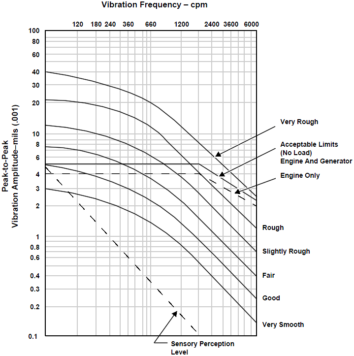
Engines produce vibrations due to combustion forces, torque reactions, structural mass and stiffness combinations, and manufacturing tolerances on rotating components. These forces create a range of undesirable conditions, ranging from unwanted noise to high stress levels and ultimate failure of engine or generator components. Vibrating stresses reach destructive levels at engine speeds where resonance occurs. Resonance occurs when system natural frequencies coincide with engine excitations. The total engine-generator system must be analyzed for critical linear and torsional vibration. (See chart 1)
Chart 1
Vibration Effects
There will always be some vibration in rotating machinery like an operating gen set, so it is good practice to specify isolation of the unit. The unit should not rest directly on rock, soil, steel or concrete. These materials can transmit vibrations long distances.
Resonance of certain gen set frequencies with the natural frequencies of building structural members can cause damage to some types of construction.
Vibration measured is approximately a sum of all vibration sources. Testing can determine sources.
Separating the gen set from the surroundings can be done with a bulk isolator such as an inertia block or with commercial isolators.
The bulk isolator is the more expensive and elaborate of the two systems. It consists of a massive block on which the gen set is mounted. The block is surrounded by cork or fiberglass, separating it from the surrounding structure.
Rubber pads are sometimes used to dampen high frequencies which cause noise, but the most often-used device is the spring-type isolator. It offers about 95 percent isolation of all vibration and eliminates the need for an inertia block.
Spring isolators are placed under the gen set rails but are not bolted to the floor unless the unit is paralleled with other generator sets or is in an earthquake-prone area. Spring isolators are most effective when located directly under the engine and generator mounting feet.
Care must be taken to make sure the spring can accommodate the gen set’s weight. If the spring is compressed completely, all vibration will be directly transmitted to the structure it rests on.
Consider Idle Units
Units that are not operating can be damaged by vibrations set up by nearby operating units. Because the idled units have no oil pressure to keep internal components lubricated, the vibration can cause severe damage. Here, spring isolators can minimize vibration effects.
Fuel lines, exhaust piping and electrical connections all transmit vibrations. It is a waste of effort to provide mounting protection unless these connections are specified to have vibration-limiting connections. Each connection must be isolated with flexible connections to provide maximum vibration reduction.
Resonance of pipe systems can also be reduced by hanging supports at unequal distances. (See figure 2). To attenuate low-frequency vibrations, specify spring-type isolator pipe hangers. High-frequency vibrations can be minimized with rubber or cork cushioned hangers.
Figure 2
Specify hangers to be installed at uneven intervals to minimize pipe vibration problems.
It is possible to test complete systems to ensure vibrations are not excessive. If a structure is sensitive to vibration from gen set operation, such test should be considered before the unit is commissioned. Your CAT dealer can advise you how such tests can be carried out.
Vibration problems can cause considerable damage, and it is best solved when the specifications is written. The addition of spring isolators or an inertia block as well as flexible connections on piping and electric lines can prevent many difficulties later on.